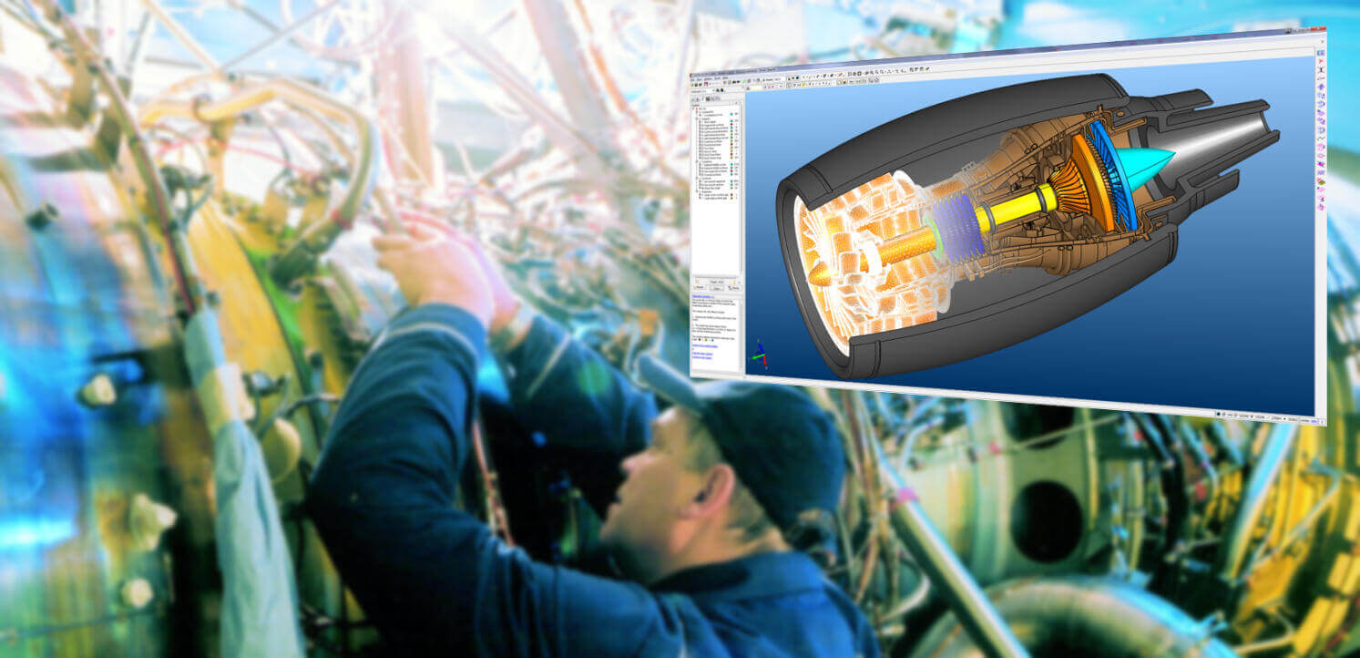
CADfix offers CAE analysts the ability to automatically and interactively repair and transform CAD geometries prior to analysis. CADfix ensures that solid or surface models are robustly translated effectively into target systems. CADfix offers a full range of import and export functionality for pre-processing CAD data from native and neutral formats.
Master Model Driven FEA, CFD, EM Solutions
With ever shortening product design cycles, the emphasis on simulation tools to provide timely results to drive the design is greater than ever. This pressure dictates FEA, CFD and EM analysis being driven off the master model CAD data. CAD provides the geometry but a great deal of analysis time is still spent working with the geometry to prepare it for analysis.
CADfix for Geometric Exchange is uniquely positioned in the CAD to CAE data flow with its ability to read and write multiple geometric formats, repair and heal poor quality geometry and de-feature and simplify complex geometric definition. In the end, CAE analysts are starting with much more robust geometric definitions for their analytical needs
Defeaturing tools
CADfix tools let you remove different features of a CAD model that are not required for the next stage of your design or manufacturing process. Functions such as holes, fillets, chamfers, small bodies and internal elements can be removed using CADfix tools. CADfix automatically recognizes certain functions, even without history such as in a STEP format. The other functions can be identified by their size or by a function of semi-automatic selection, with tangency propagation .
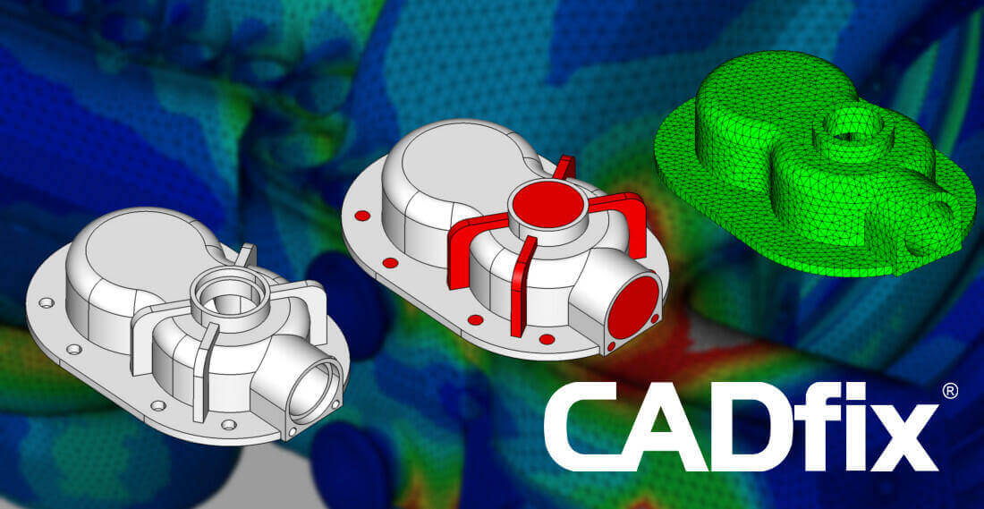
Automatic detection and removal of automatic function from a STEP file for simulation
Complex Zone Parameterisation
Modern CAD systems often provide complex geometry for mesh generation tools. With small, narrow faces, fillets, and detailed features, meshers are often able to refine their grids in these areas, leading to extremely dense meshes with inconsistent feature sizing in these areas.
One solution is to simplify the model, to remove or collapse features or to merge small faces to neighbors, but the resulting geometry used for the simulation is often different from the actual design, which can lead to results that are not representative of the original intent of the engineer
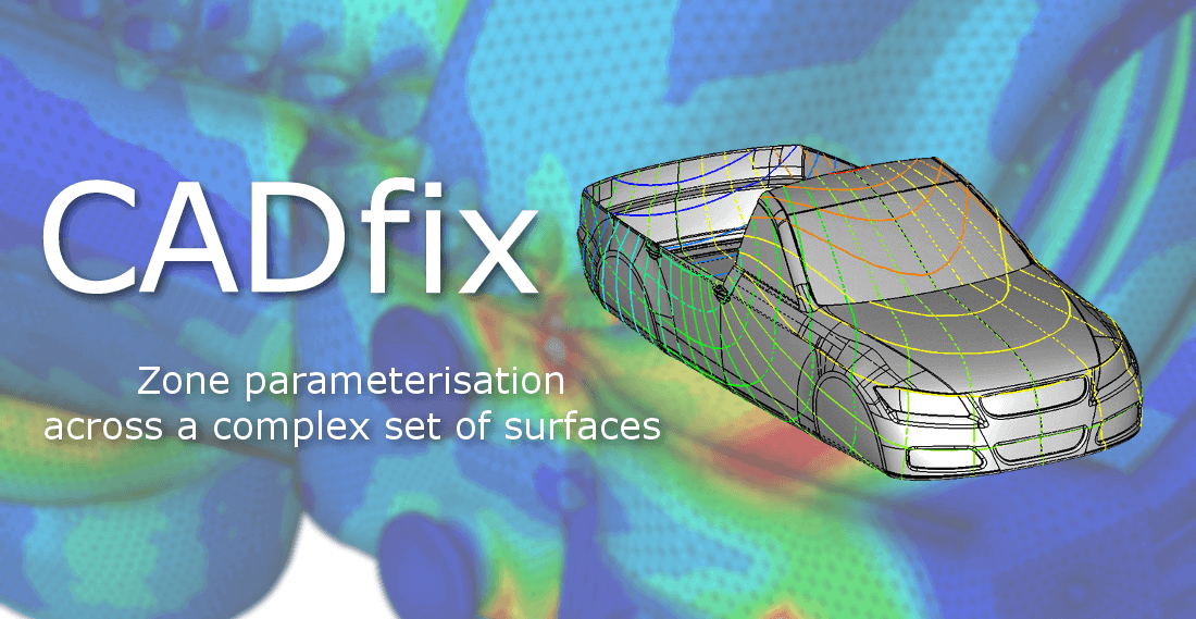
Zone parameterisation across a complex set of surfaces
This is where the CADfix complex area parameter tool is used. This tool allows users to parameterize models based on existing geometric boundaries, allowing regular mesh sizes to be placed beyond these challenging surfaces.
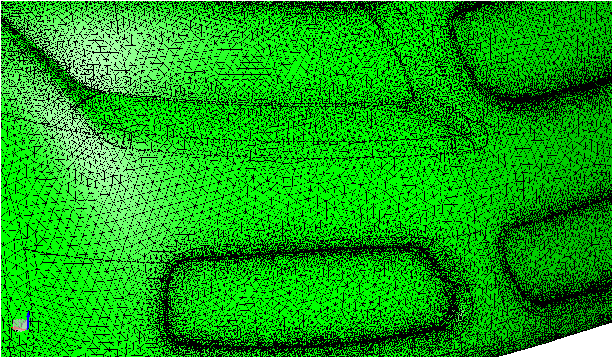 Meshing across surface edges using a zoned parameterisation
Cross-field based quad splitting
LQuad meshing of surfaces is commonplace in the meshing community, but for complex face definitions created by modern CAD systems, obtaining a high quality quad mesh can be problematic. By subdividing a complex face into smaller quadrilateral faces, meshing systems can more easily place a regular quad grid in these smaller faces, maintaining a higher quality of mesh across the entire face. The new CADfix 12 “Split faces into quads” tool automates the process of robustly identifying suitable regions and splitting a CAD face into quad patches for meshing.
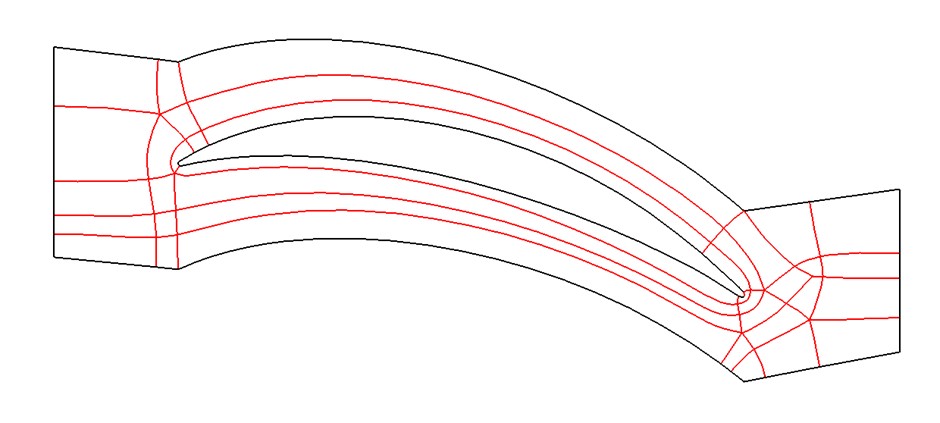
Quad subdivision of a complicated surface ready for meshing
Hex-skin partitioning tool for hybrid meshing
EnMoving from structured surface to structured volume meshes, the automatic hex-skin tool allows users to automatically partition a model, using ITI’s CADfix 3D Medial Object Technology, into regions suitable for producing a structured hex mesh layer close to the surface and an unstructured tet-mesh elsewhere.

Auto hex-skin subdivision and hybrid meshing
The hex-skin approach to meshing means that singularities are not propagated through a mesh, as they can be in fully structured hex mesh volumes, and it allows for appropriate mesh sizing close to the boundary. This technology was recently presented at the NAFEMS UK Conference and has benefited from developments as part of ongoing Innovate UK and industrial research projects.


